SIEMENS Portable Case & 6-DOF Stewart Platform
A didactic plug-and-play Siemens controller case driving a 6-DOF Stewart Platform in closed-loop with auto-tuned PID position control
The Challenge
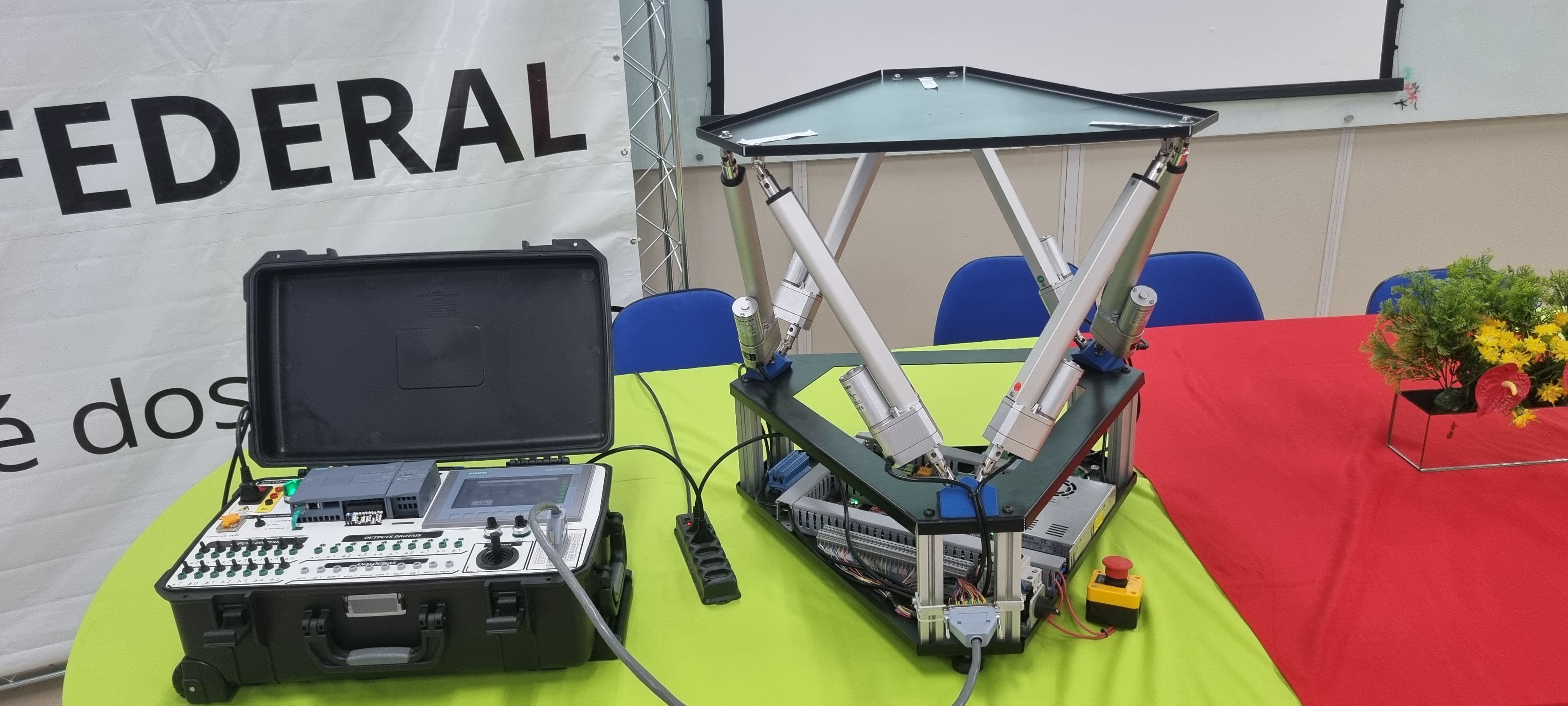
Two prototypes, designed and built from scratch to work as a single integrated system. The first is a portable controller case — a self-contained, plug-and-play Siemens PLC + HMI kit, flexible enough to drive almost any industrial plant, with all the I/O, power supply, network and operator interface mounted into a single rugged Pelican-style case. The second is a 6-DOF Gough-Stewart Platform driven by six independent linear electric actuators, designed as the controlled plant. The two devices had to be electrically and logically integrated through a single DB-37 connector, while still being usable independently in any other application. The platform had to be fully controllable in closed loop, with each actuator individually positioned through PID, and the case had to expose every PLC signal in a clean, didactic and industrial-grade front panel — switches, LEDs, banana terminals, joystick, potentiometers, RJ45 and Wi-Fi access — without losing portability.
The Controller Case
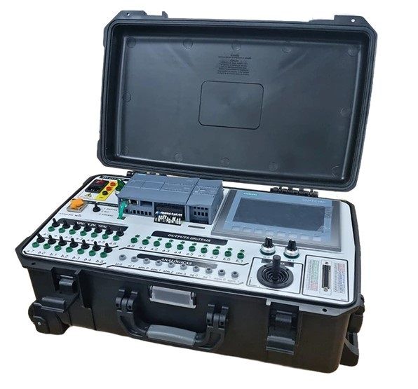
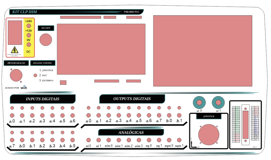
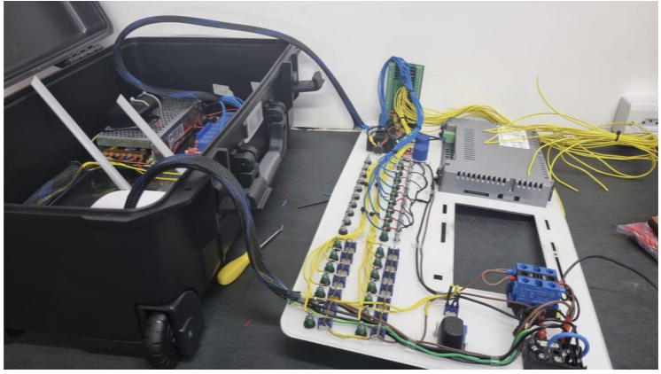
Built around a Siemens S7-1200 CPU 1215C with an SM 1234 analog expansion module — adding the analog channels needed to read the six actuator position feedback signals — and a Siemens KTP 700 Basic 7" touch HMI programmed in WinCC. Both devices share an internal Ethernet TCP/IP network through a small router that also exposes the PLC over Wi-Fi for remote programming. The entire kit lives inside a Pelican-style MP0055 case, with a 5 mm laser-cut acrylic front panel and a custom-printed adhesive following the Siemens visual language. Every PLC I/O is broken out to a banana terminal with its own illuminated switch and LED indicator: 14 digital inputs, 10 digital outputs, 4 analog inputs (selectable between joystick, precision potentiometers and external source), 2 analog outputs and 6 expansion analog inputs. A DB-37 connector exports every relevant signal in a single cable, an RJ45 connector allows easy network expansion, and an 8-channel relay board sits between the PLC outputs and the field, handling the analog-source selector switching and providing four spare relays for prototyping. Internally the case carries a 24 V / 10 A switching power supply, a 24V→10V adjustable regulator, a circuit breaker, an emergency stop, fuses on every PLC output to protect against load short-circuits, and a clean cable routing with proper crimping and identification. The full electrical schematic was drafted in EPLAN and went through 35 revisions before fabrication.
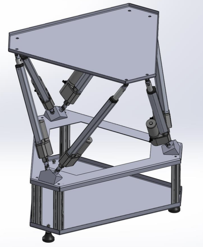
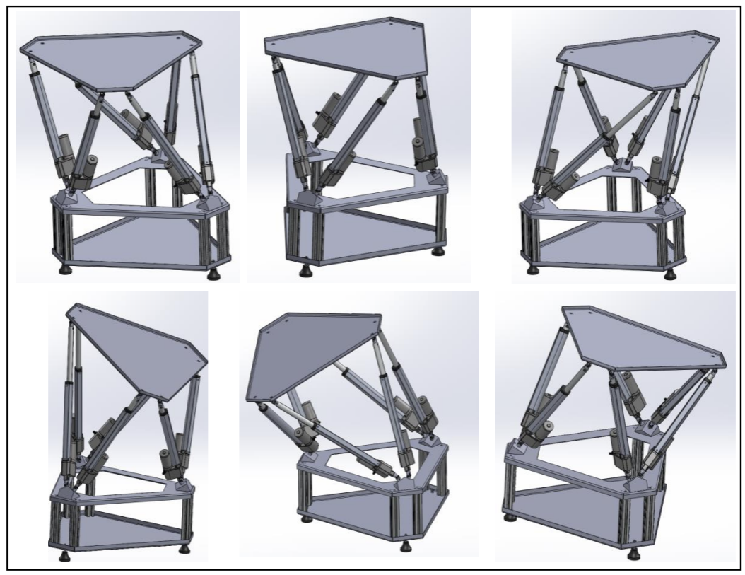
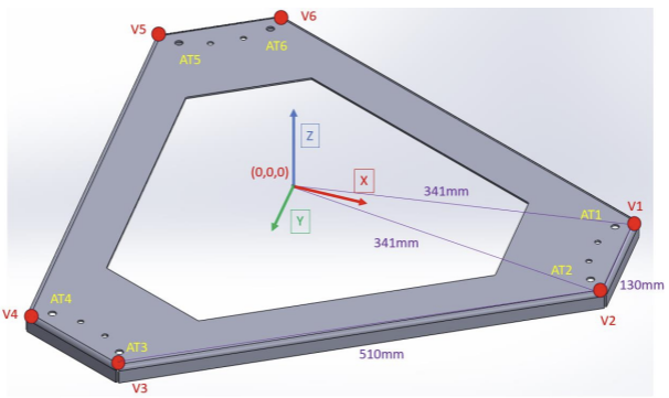
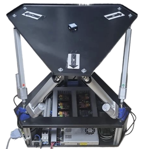
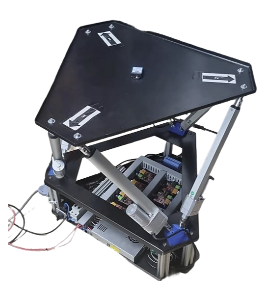
The Stewart Platform
A Gough-Stewart-style parallel manipulator built from three 2 mm steel plates (lower base, central support and upper movable plate) joined by 30×30 mm structural aluminum profiles. The three plates were fully drawn in SolidWorks before any cut, with the geometry validated through 3D simulations of the full motion envelope. The platform is driven by six independent linear electric screw actuators (24 V, 60 mm/s, 80 N, 250 mm of useful stroke). These were chosen over pneumatic or hydraulic alternatives for three reasons: linearity, low cost and — most importantly — built-in resistive position feedback (an internal element that varies its resistance with the actuator position, giving a 0–10 V analog signal directly back to the PLC), which removes the need for any external linear encoder. Each actuator is mounted at roughly 60° to the XY plane through 3D-printed brackets sized from coordinate calculations done in trigonometry / linear algebra over the SolidWorks model. Double kardan joints connect the actuator shafts to the upper plate, allowing two-axis articulation without binding. Parlock nuts prevent loosening under vibration, and adjustable feet correct the inevitable manufacturing imperfections. Decomposing the 80 N actuator force at the 60° mounting angle yields ~69 N per actuator, so the platform supports up to ~414 N (~42.2 kgf) of vertical thrust — minus the 4.1 kg of the upper plate, ~38 kg of net payload.
Power & Signal Chain
Bridging a 24 V industrial PLC to six 5 V-controlled DC motor drivers required a custom signal-conditioning chain, designed and revised through dedicated EPLAN drawings. Each actuator is driven by an XY-15AS DC motor driver (mosfet-based, up to 20 A, 100 kHz PWM). The drivers expect 5 V logic on their IN1, IN2 (direction) and PWM (speed) inputs, while the S7-1200 outputs 24 V. The bridge is built with C309 optocoupler boards: NPN boards convert 24 V → 5 V, PNP boards convert non-24 V → 5 V, both in mirrored pairs so that the two direction bits stay correctly inverted regardless of the PLC signal state. Because the S7-1200 only has four hardware PWM outputs and the platform needs six, two LC-LM358-PWM2V analog-to-PWM converter boards were added: they take a 0–10 V analog signal from the PLC and translate it into a 24 V PWM with proportional duty cycle, which then goes through its own optocoupler stage before reaching the driver. The result is two control paths in parallel — direct PWM for four actuators (Ligação A) and analog-to-PWM for the remaining two (Ligação B) — both behaviorally identical from the PID's point of view. The 0–10 V position feedback from each actuator goes straight into the PLC analog input, closing the loop entirely inside the controller without any extra ADC.
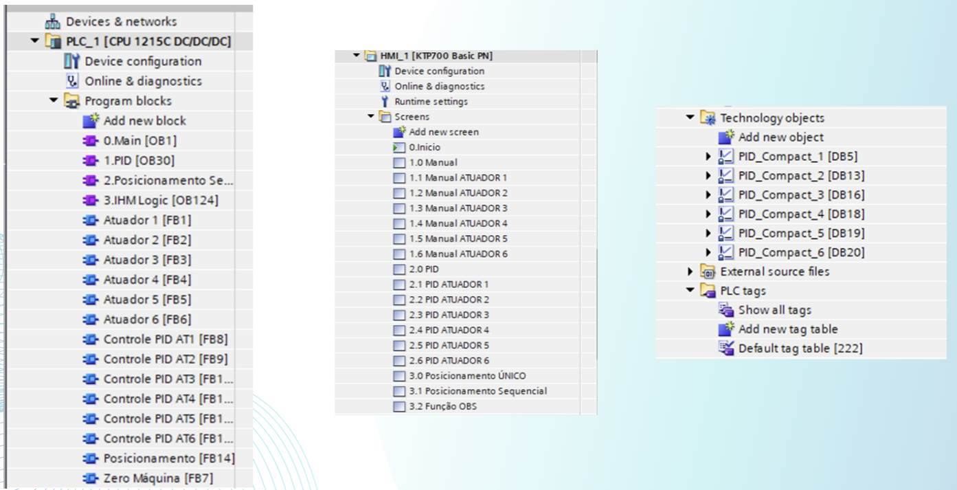
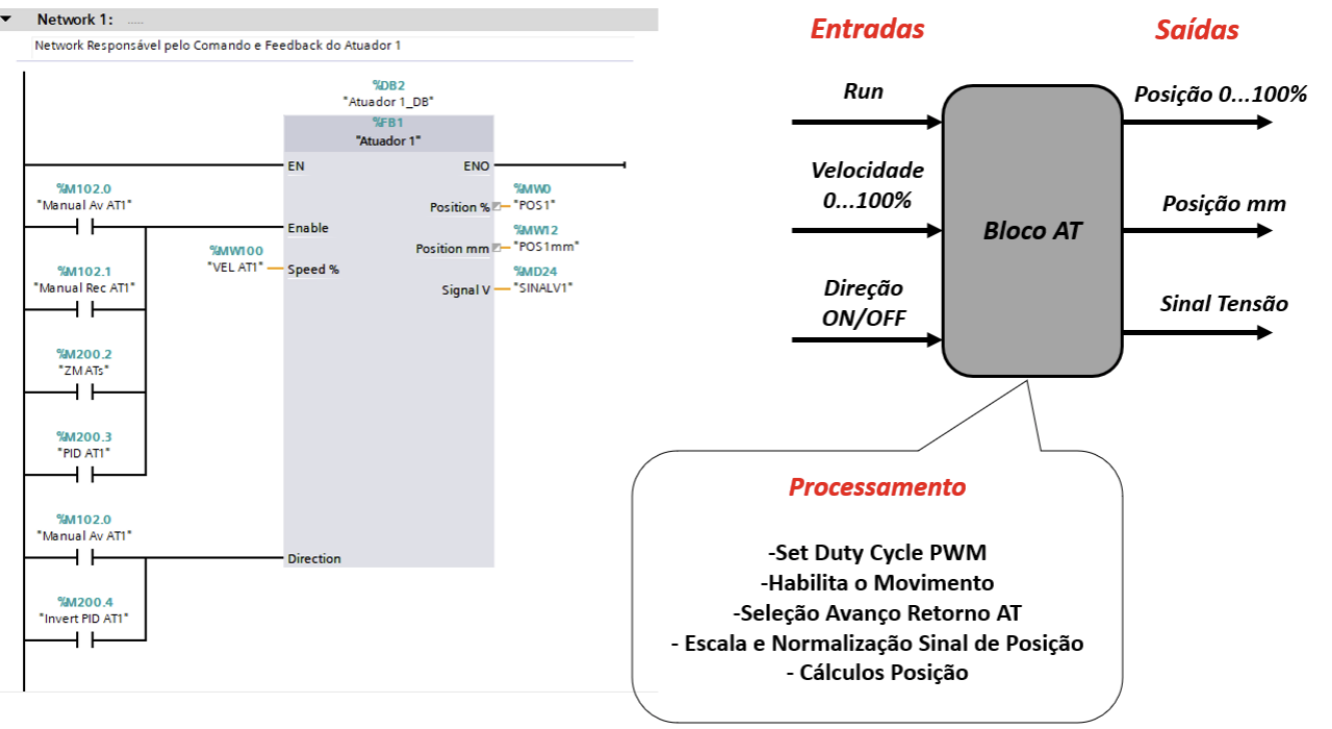
PLC Programming
All programming was done in TIA Portal STEP 7 with a strict modular philosophy — every recurring behavior was condensed into a Function Block (FB) so the main routines stay short, readable and reusable. The program tree is split into four organizational blocks (Main, PID, Sequential Positioning, HMI Logic) and a series of dedicated FBs: • Atuador 1–6 (FB1–FB6) — one block per actuator. Inputs: Run, Speed, Direction. Internally it sets the PWM duty cycle, enables movement, picks forward/return direction, scales the raw analog feedback into normalized 0–100% / mm position values. • Controle PID AT1–AT6 (FB8–FB13) — one PID wrapper per actuator. Each one drives a native PID_Compact technology object (DB5, DB13, DB16, DB18, DB19, DB20), with auto-tuning run individually per actuator to extract optimal Kp, Ti and Td values. Inputs: Run, Reference, current Position. Outputs: Speed, Direction, End signal. • Posicionamento (FB14) — generic block that accepts six target positions and triggers all six PIDs simultaneously, with tolerance checking on the final condition. • Zero Máquina (FB7) — drives every actuator to its retracted reference position at full speed. On top of these blocks, three demonstration routines were implemented: manual jog of every actuator, single/sequential positioning cycles with PID, and an Observatory Function that, given an angle and a direction, computes the six target positions and orients the upper plate as a real telescope mount would.
PID Tuning & System Identification
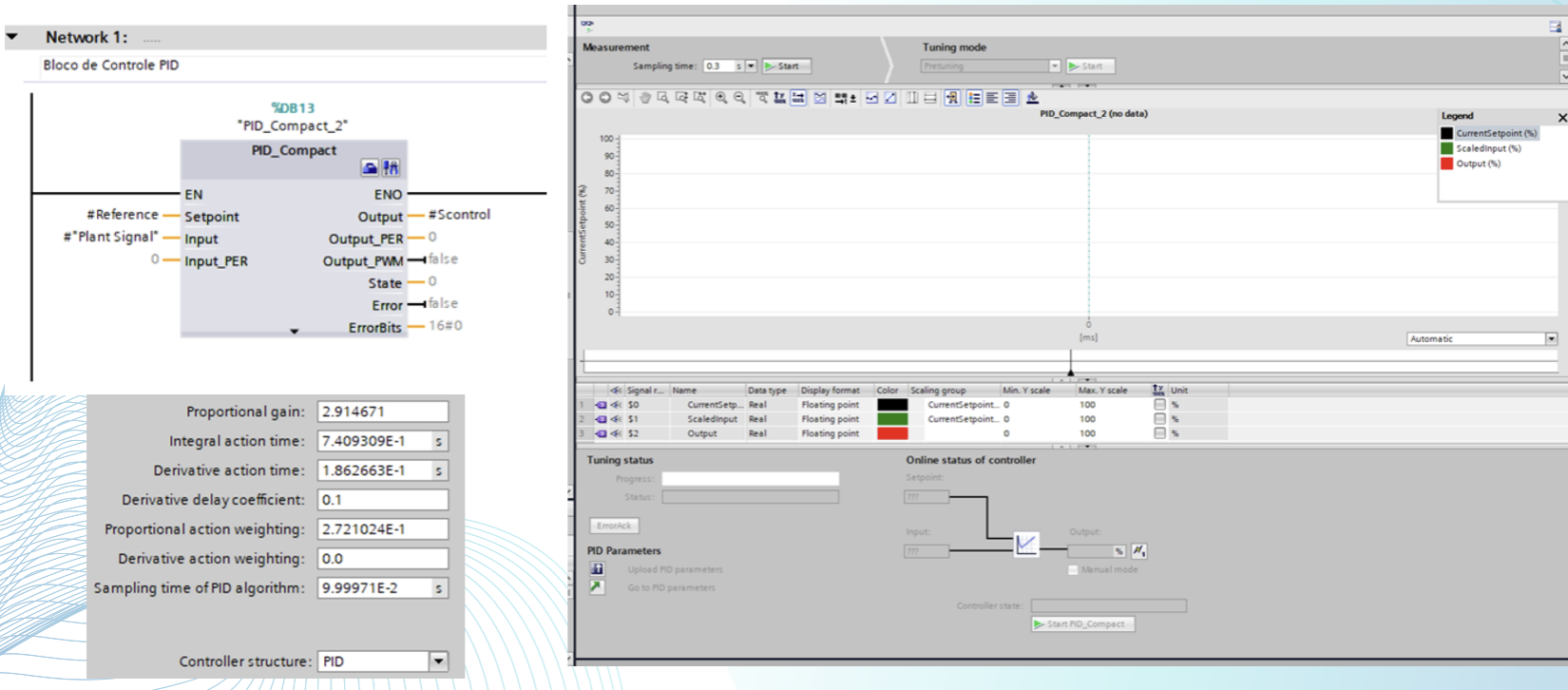
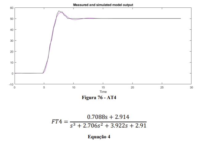
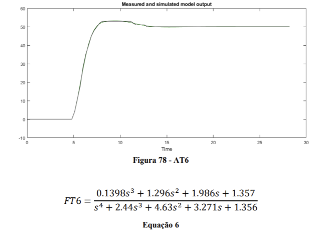
The PID_Compact block from TIA Portal supports auto-tuning by injecting test signals and iteratively adjusting parameters. Each of the six actuators was tuned independently — and although they're physically identical, the resulting Kp / Ti / Td values come out different (e.g. AT1: Kp=2.91, Ti=0.74 s, Td=0.19 s vs AT2: Kp=1.51, Ti=1.22 s, Td=0.27 s). This is expected: small mechanical non-linearities — slight load differences, mounting angles, gear backlash, electrical induction — make each actuator a slightly different plant. To characterize the system, position data was sampled at ~3 Hz over a step input on each actuator, exported to MATLAB and processed through System Identification, which iteratively added poles and zeros to fit empirical transfer functions to the measured response. The resulting models reach 93.78%–98.86% accuracy. As an example, AT2 was identified as a clean second-order system: FT2 = 1.265 / (s² + 1.229s + 1.263), at 97.35% precision. The sequential positioning routine performed reliably; the observatory function achieved at most 1° of orientation error. Simultaneous actuation of more than three actuators occasionally introduced cross-coupling effects (one actuator's motion perturbs the others' loops) — a known limitation of decoupled per-actuator PID on a fully-coupled parallel manipulator, which would be solved with a coupled multivariable controller.
Results
Two fully functional, electrically integrated and independently usable prototypes: • A portable Siemens controller case that can drive almost any small/medium industrial plant out of the box, with every PLC signal exposed on the front panel and a Wi-Fi link for remote programming. • A 6-DOF Stewart Platform with auto-tuned per-actuator PID position control, ~38 kg of usable payload, ~1° accuracy on the observatory routine, and identified transfer functions reaching 98.86% model fidelity. The system supports manual jog, single-position PID, sequential positioning cycles, machine zero, and a real-application observatory routine that orients the upper plate as a telescope mount would. Both devices can be unplugged and used separately — the case as a generic PLC kit, the platform as a controlled plant for any other controller — preserving the original plug-and-play design intent.